TM-9-2320-260-34-2 - Page 387 of 863
TM 9-2320-260-34-2
15-87. 400 Hz CONVERTER HARNESS CONDUIT REPLACEMENT
THIS TASK COVERS:
a. Removal
b. Installation
INITIAL SETUP
APPLICABLE MODELS
REFERENCES (TM)
M820, M820A2
TM 9-2320-260-10
TEST EQUIPMENT
TM 9-2320-260-20
TM 9-2320-260-34P-2
Multimeter (Appendix B, Item 115)
EQUIPMENT CONDITION
TOOLS
●
External power source disconnected
General mechanic’s tool kit
(Appendix B, Item 1)
(TM
9-2320-260-10).
●
Battery ground cable disconnected
Tool kit, electrical (Appendix B, Item 106)
(TM
9-2320-260-20).
●
Outlet box removed (para. 15-88).
●
Converter junction box removed (para. 15-86).
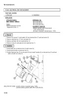
1. Remove six screws (2) and clamps (3) from conduits (7) and (4).
2. Remove nuts (8) and (5) from coupling (l).
3. Remove coupling (1) from conduits (7) and (4).
4. Remove conduits (7) and (4) from van body (6).
1. Position nuts (8) and (5) on conduits (7) and (4).
2. Install coupling (1) on conduits (7) and (4).
3. Install conduits (7) and (4) on van body (6) with six clamps (3) and screws (2).
4. Tighten nuts (8) and (5) on coupling (1).
15-326
Back to Top


