TM-9-2320-260-34-2 - Page 669 of 863
TM 9-2320-260-34-2
Section VI. POWER DIVIDER AND DRIVE MAINTENANCE
16-46. POWER DIVIDER AND DRIVE MAINTENANCE INDEX
PARA.
TITLE
PAGE
NO.
NO.
16-47.
Power Divider and Drive Replacement
16-270
16-48.
Power Divider Repair
16-278
16-49.
Drive Repair
16-296
16-50.
Power Divider Governor Control Valve Replacement
16-299
16-47. POWER DIVIDER AND DRIVE REPLACEMENT
THIS TASK COVERS:
a. Removal
b. Installation
INITIAL SETUP
APPLICABLE MODELS
M816
TOOLS
General mechanic’s tool kit
(Appendix B, Item 1)
Lifting device
supports
MATERIALS/PARTS
Gasket (Appendix D, Item 102)
Cotter pin (Appendix D, Item 21)
Two locknuts (Appendix D, Item 182)
Two sleeves (Appendix D, Item 511)
Four cotter pins (Appendix D, Item 48)
Six lockwashers (Appendix D, Item 224
Six lockwashers (Appendix D, Item 215)
Antiseize tape (Appendix C, Item 50)
REFERENCES (TM)
LO 9-2320-261-12
TM 9-2320-260-10
REFERENCES (TM) (Contd)
TM 9-2320-260-20
TM 9-2320-260-34P-2
EQUIPMENT CONDITION
●
Power divider and drive oil drained
(LO 9-2320-260-12).
●
Air reservoirs drained (TM 9-2320-260-10).
●
Transfer-to-power divider propeller shaft removed
(TM 9-2320-260-20).
●
Power divider-to-rear winch drive propeller shaft
removed (TM 9-2320-260-20).
●
Power divider-to-hydraulic pump propeller shaft
removed (TM 9-2320-260-20).
GENERAL SAFETY INSTRUCTIONS
●
Do not disconnect air lines before draining air
reservoirs.
●
All personnel must stand clear during lifting
operations.
●
Ensure lifting capacity is greater than weight of
power cylinder.
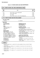
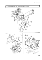
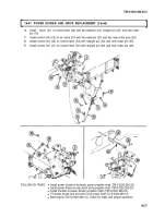
1. Remove two cotter pins (1), control link (5), and two washers (6) from air valve (9). Discard
cotter pins (1).
2. Remove cotter pin (2), straight pin (7), two washers (3), and clevis (4) from control lever (8).
Discard cotter pin (2).
3. Remove cotter pin (14), straight pin (15), and control link (17) from control lever (16). Discard
cotter pin (14).
4. Remove cotter pin (13), straight pin (11), and control link (10) from control lever (12). Discard
cotter pin (13).
16-270
Back to Top


