TM-9-2320-272-23-1 - Page 1263 of 1313
CONTROL PANEL LIGHTS WORK, SYSTEM FAILS TO INFLATE OR DEFLATE - Continued
STEP
9.
IS THERE CONTINUITY BETWEEN PRESSURE SWITCH PINS A AND B WHEN AIR SYSTEM IS AT
NORMAL OPERATING PRESSURE?
a.
Refer to point to point schematics.
T0426DAA
PRESSURE
SWITCH
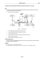
Figure 8.
Pressure Switch.
b.
Connect multimeter red lead to pressure switch pin A.
c.
Connect multimeter black lead to pressure switch at pin B.
d.
Use shop air pressure or start and run engine until air pressure reaches 112-120 psi while monitoring
the instrument cluster air pressure gauge.
e.
Pressure switch should close.
f.
Meter reading should be less than 20 ohms.
CONDITION/INDICATION
IS THERE CONTINUITY BETWEEN PRESSURE SWITCH PINS A AND B WHEN AIR SYSTEM IS AT
NORMAL OPERATING PRESSURE?
DECISION
YES - Go to Step (10).
NO - Replace pressure switch (Volume 2, WP
0324). Go to Step (11) to verify problem is solved.
TM 9-2320-272-23-1
0149
0149-10
Back to Top


