TM-9-2320-272-23-1 - Page 758 of 1313
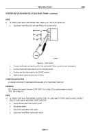
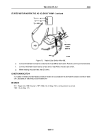
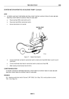
STARTER MOTOR INOPERATIVE; NO SOLENOID THUMP - Continued
STEP
6.
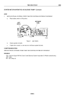
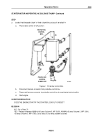
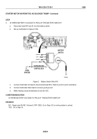
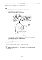
IS THERE BATTERY VOLTAGE AT HARNESS CONNECTOR PIN C?
a.
Place battery switch to OFF.
T0711DAA
A
B
C
D
E
F
G
CONNECTOR
HARNESS
VOM
PROTECTIVE
CONTROL
BOX
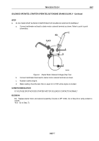
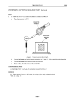
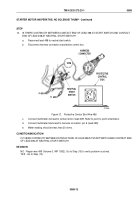
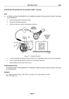
Figure 6.
Protective Control Box Wire 81.
b.
Connect multimeter red lead to harness connector, pin C (lead 81). Refer to point to point schematics.
c.
Connect multimeter black lead to a known good ground.
d.
Meter reading should be between 22 and 26 VDC.
CONDITION/INDICATION
IS THERE BATTERY VOLTAGE AT HARNESS CONNECTOR PIN C?
DECISION
NO - Repair wire 81 (Volume 3, WP
0352). Go to Step (15) to verify problem is solved.
YES - Go to Step (7).
TM 9-2320-272-23-1
0088
0088-7
Back to Top

