TM-9-2320-272-23-1 - Page 765 of 1313
STARTER MOTOR INOPERATIVE; NO SOLENOID THUMP - Continued
STEP
13.
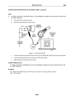
IS THERE CONTINUITY BETWEEN PIN F AT HARNESS CONNECTOR AND CONTACT END OF LEAD 566
AT ALTERNATOR?
a.
Reconnect lead 499 to neutral start switch.
b.
Disconnect lead 566 at alternator.
c.
Disconnect harness connector at protective control box.
T0719DAA
A
B
C
D
E
F
G
HARNESS
CONNECTOR
PROTECTIVE
CONTROL
BOX
VOM
5
566
3
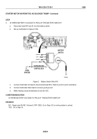
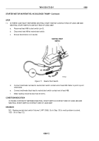
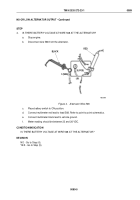
Figure 13.
Alternator Wire 566.
d.
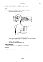
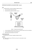
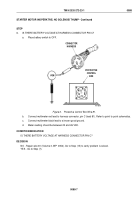
Connect multimeter red lead to harness connector, pin F (lead 566). Refer to point to point schematics.
e.
Connect multimeter black lead to contact end of lead 566 at alternator.
f.
Meter reading should be less than 20 ohms.
CONDITION/INDICATION
IS THERE CONTINUITY BETWEEN PIN F AT HARNESS CONNECTOR AND CONTACT END OF LEAD 566
AT ALTERNATOR?
DECISION
NO - Repair wire 566 (Volume 3, WP
0352). Go to Step (15) to verify problem is solved.
YES - Go to Step (14).
TM 9-2320-272-23-1
0088
0088-14
Back to Top

