TM-9-2320-272-23-1 - Page 813 of 1313
BLACKOUT DRIVE OR BLACKOUT MARKER LIGHT INOPERATIVE - Continued
STEP
4.
IS THERE BATTERY VOLTAGE AT NON-OPERATING BLACKOUT LAMP CONNECTOR?
a.
Place battery switch to OFF position.
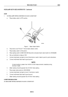
T0758DAA
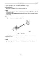
Figure 4.
Blackout Light Assemblies.
b.
Disconnect circuit 19 wire from non-operating blackout drive light.
c.
Disconnect circuit 20 wire from non-operating left and right front composite lights.
d.
Disconnect circuit 24 wire from non-operating left and right rear composite lights.
e.
Place battery switch to ON position.
f.
Place lighting switch to B.O. DRIVE position.
g.
Set up multimeter to measure VDC.
NOTE
Perform the following Steps at non-operating blackout light.
h.
Connect multimeter red lead to disconnected wire. Refer to point to point schematics.
i.
Connect multimeter black lead to good ground.
j.
Meter reading should be greater than 18 VDC for each reading. Note reading.
CONDITION/INDICATION
IS THERE BATTERY VOLTAGE AT NON-OPERATING BLACKOUT LAMP CONNECTOR?
TM 9-2320-272-23-1
0094
0094-4
Back to Top


