TM-9-2320-272-23-1 - Page 846 of 1313
NO LIGHTS OPERATE WITH DIRECTIONAL SIGNAL CONTROL LEVER IN ANY POSITION - Continued
C
B
A
K
E
T1027DAA
F
N
M
L
H
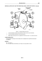
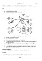
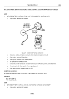
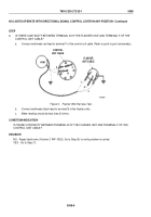
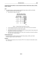
Figure 2.
Main Lighting Switch Connector.
b.
Remove lighting switch from instrument panel and disconnect harness
connector (Volume 2, WP
0315).
c.
Place battery switch to ON position.
d.
Connect multimeter red lead to connector socket pin F. Refer to point to point schematics.
e.
Connect multimeter black lead to good ground.
f.
Meter reading should be greater than 18 VDC.
CONDITION/INDICATION
IS THERE BATTERY VOLTAGE AT MAIN LIGHT SWITCH HARNESS CONNECTOR?
DECISION
NO - Go to Step (3).
YES - Go to Step (4).
STEP
3.
IS WIRING HARNESS IN GOOD CONDITION?
a.
Place battery switch to OFF position.
C
B
A
K
E
T1027DAA
F
N
M
L
H
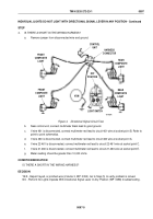
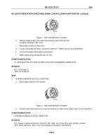
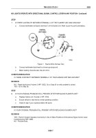
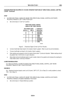
Figure 3.
Main Lighting Switch Connector.
b.
Visually check wiring harness for loose connections or broken wiring. Refer to point to point schematic.
CONDITION/INDICATION
IS WIRING HARNESS IN GOOD CONDITION?
DECISION
NO - Repair or replace broken wire (Volume 3, WP
0352). Go to Step (9) to verify problem is solved.
YES - Notify supervisor. Action may not be possible at this level of maintenance.
TM 9-2320-272-23-1
0098
0098-3
Back to Top

