TM-9-2320-272-23-2 - Page 757 of 1417
INSTALLATION
1.
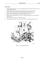
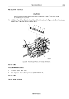
Apply antiseize compound to four mounting studs (Figure 4, Item 6) and install gasket (Figure 4, Item 12) and
turbocharger (Figure 4, Item 1) on exhaust manifold (Figure 4, Item 7) with four nuts (Figure 4, Item 13) to
25
lb-ft (34 N·m).
CAUTION
Turbocharger must be lubricated with clean engine oil prior to starting engine, or bearing
damage may result.
2.
With a small funnel positioned in turbocharger oil supply hole (Figure 4, Item 2), pour 2 to 3 ounces
(57
to
85
grams) of clean engine oil into turbocharger (Figure 4, Item 1).
3.
Spin impeller/turbine blades (Figure 4, Item 14) by hand to coat bearings with oil.
4.
Connect exhaust pipe (Figure 4, Item 8) to turbocharger (Figure 4, Item 1) and tighten clamp
(Figure
4,
Item
9).
5.
Connect air intake tube (Figure 4, Item 11) to turbocharger (Figure 4, Item 1) and tighten clamp
(Figure
4,
Item
10).
NOTE
•
Perform Steps (6) and (7) for early model engines.
•
Perform Steps (8) and (9) for late model engines.
•
Wrap all male pipe threads with antiseize tape before installation.
6.
Install connector (Figure 4, Item 4) on oil cooler (Figure 4, Item 5).
7.
Install oil supply hose (Figure 4, Item 3) on turbocharger (Figure 4, Item 1) and connector (Figure 4, Item 4).
8.
Install o-ring (Figure 4, Item 16) and connector (Figure 4, Item 15) on oil cooler (Figure 4, Item 5).
9.
Install oil supply hose (Figure 4, Item 3) on turbocharger (Figure 4, Item 1) and connector (Figure 4, Item 15).
TM 9-2320-272-23-2
0249
0249-6
Back to Top

