TM-9-2320-272-23-3 - Page 1001 of 1469
INSTALLATION
1.
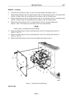
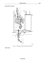
Install three fittings (Figure 3, Item 2) on quick-release valve (Figure 3, Item 1).
2.
Install two fittings (Figure 3, Item 2) and fitting (Figure 3, Item 5) on double check valve No. 3
(Figure
3,
Item
15).
3.
Install two fittings (Figure 3, Item 2) and fitting (Figure 3, Item 5) on double check valve No. 4
(Figure
3,
Item
12).
4.
Install quick-release valve (Figure 3, Item 1) on access box cover (Figure 3, Item 16) with two screws
(Figure
3,
Item
17), washers (Figure 3, Item 14), and locknuts (Figure 3, Item 13).
5.
Install double check valve No. 3 (Figure 3, Item 15) on access box cover (Figure 3, Item 16) with screw
(Figure
3,
Item
17), washer (Figure 3, Item 14), and locknut (Figure 3, Item 13).
6.
Install double check valve No. 4 (Figure 3, Item 12) on access box cover (Figure 3, Item 16) with screw
(Figure
3,
Item
17), washer (Figure 3, Item 14), and locknut (Figure 3, Item 13).
7.
Connect air lines (Figure 3, Items 4, 6, and 7) to quick-release valve (Figure 3, Item 1).
8.
Connect air lines (Figure 3, Items 3, 7, and 8) to double check valve No. 3 (Figure 3, Item 15).
9.
Connect air lines (Figure 3, Items 8, 9, and 10) to double check valve No. 4 (Figure 3, Item 12).
10.
Install access box cover (Figure 3, Item 16) on step box access (Figure 3, Item 11) with eight lockwashers
(Figure 3, Item 18) and screws (Figure 3, Item 19).
M6264DAA
6
9
5
5
4
3
2
1
13
12
2
11
7
8
10
16
14
2
18
19
17
15
Figure 3.
Double Check Valve Installation.
TM 9-2320-272-23-3
0477
0477-4
Back to Top


