TM-9-2320-272-23-3 - Page 1013 of 1469
CLEANING AND INSPECTION - Continued
4.
Inspect inner and outer bearings (TM 9-214). Replace if damaged.
5.
Inspect inner and outer bearing cups (TM 9-214). Replace if damaged.
NOTE
Perform Steps (6) and (7) only if bearing cups are to be replaced.
6.
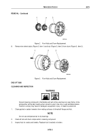
Remove bearing cups from hub by tapping alternately on outer edge.
7.
Press inner bearing cup and outer bearing cup into hub. Ensure bearing cups are seated.
8.
Inspect drum for deep grooves. Replace drum if grooves are deeper than 1/32 in. (0.79 mm).
END OF TASK
INSTALLATION
1.
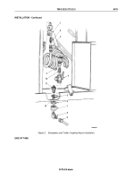
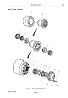
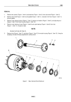
Pack inner and outer bearings (Figure 4, Items 4 and 7) with automotive and artillery grease (TM 9-214).
2.
Pack inner rubber section of inner oil seal (Figure 4, Item 3) with automotive and artillery grease (TM
9-214).
3.
Install hub (Figure 4, Item 2) in drum (Figure 4, Item 1).
4.
Press wheel studs (Figure 4, Item 8) through drum (Figure 4, Item 1) and into hub (Figure 4, Item 2). Ensure
studs are seated.
5.
Install inner bearing (Figure 4, Item 4) and inner bearing oil seal (Figure 4, Item 3) into hub (Figure 4, Item 2).
Ensure inner bearing oil seal is seated.
NOTE
Assistant will help with Step (4).
6.
Install hub (Figure 4, Item 2) and drum (Figure 4, Item 1) on spindle (Figure 4, Item 9).
7.
Install outer bearing (Figure 4, Item 7) on spindle (Figure 4, Item 9) with nut (Figure 4, Item 10). While rotating
hub (Figure 4, Item 2), tighten nut 50 lb-ft (68 N·m).
8.
Back out nut (Figure 4, Item 10) 1/6 to 1/4 turn so washer (Figure 4, Item 12) can be positioned to spindle
(Figure 4, Item 9) and adjusting pin (Figure 4, Item 11).
9.
Install washer (Figure 4, Item 12) and locknut (Figure 4, Item 13) on spindle (Figure 4, Item 9). Tighten locknut
250 to 400 lb-ft (339 to 542 N·m).
10.
Apply silicone rubber adhesive to mating surfaces of driveshaft flange (Figure 4, Item 14).
11.
Install gasket (Figure 4, Item 17) and driveshaft flange (Figure 4, Item 14) on hub (Figure 4, Item 2) with ten
lockwashers (Figure 4, Item 16) and screws (Figure 4, Item 15). Tighten screws 60 to 100 lb-ft (81 to 136 N·m).
TM 9-2320-272-23-3
0479
0479-4
Back to Top


