TM-9-2320-272-23-3 - Page 1011 of 1469
REMOVAL
1.
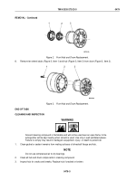
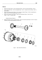
Remove ten screws (Figure 1, Item 11) and lockwashers (Figure 1, Item 12) from drive flange
(Figure
1,
Item
10) and hub (Figure 1, Item 2). Discard lockwashers.
2.
Install two screws (Figure 1, Item 11) in two threaded holes (Figure 1, Item 13) to separate drive flange
(Figure
1,
Item
10) from hub (Figure 1, Item 2).
3.
Remove drive flange (Figure 1, Item 10) and gasket (Figure 1, Item 9), if present, from hub (Figure 1, Item 2).
Discard gasket.
4.
Remove two screws (Figure 1, Item 11) from drive flange (Figure 1, Item 10).
5.
Remove outer bearing locknut (Figure 1, Item 8), bearing nut washer (Figure 1, Item 7), bearing adjusting nut
(Figure 1, Item 6), and outer bearing (Figure 1, Item 5) from spindle (Figure 1, Item 4).
6.
Remove hub (Figure 1, Item 2) and drum (Figure 1, Item 1) from spindle (Figure 1, Item 4).
M9707DAA
1
2
3
4
5
6
7
8
9
10
11
12
13
Figure 1.
Front Hub Drum Removal.
7.
Remove inner bearing oil seal (Figure 2, Item 1) and inner bearing (Figure 2, Item 2) from hub
(Figure
2,
Item
3). Discard inner bearing oil seal.
TM 9-2320-272-23-3
0479
0479-2
Back to Top


