TM-9-2320-272-23-3 - Page 1373 of 1469
REMOVAL - Continued
2.
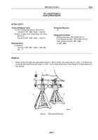
Place two jack stands (Figure 2, Item 5) under both forward-rear hubs (Figure 2, Item 9) and two jack stands
under both rear-rear hubs (Figure 2, Item 3).
3.
Loosen two bolt clamps (Figure 2, Item 8) on spring seat (Figure 2, Item 7).
4.
Remove four nuts (Figure 2, Item 4) and lockwashers (Figure 2, Item 6) from two U-bolts (Figure 2, Item 1).
Discard lockwashers.
NOTE
Step (5) applies to all models except M936 wrecker.
5.
Remove two U-bolts (Figure 2, Item 1) and upper spring saddle (Figure 2, Item 2) from rear springs
(Figure
2,
Item
10). It may be necessary to raise frame to remove U-bolts.
NOTE
Step (6) applies to M936 wrecker only.
6.
Remove two U-bolts (Figure 2, Item 1) and stabilizer beam (Figure 2, Item 11) from rear springs
(Figure
2,
Item
10).
TM 9-2320-272-23-3
0539
0539-2
Back to Top


