TM-9-2320-272-23-3 - Page 1382 of 1469
INSTALLATION - Continued
NOTE
Step (10) applies to M936 wrecker only.
10.
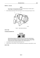
Install stabilizer beam (Figure 13, Item 6) on spring seat (Figure 13, Item 4) with two U-bolts
(Figure
13,
Item
1), four lockwashers (Figure 13, Item 3), and nuts (Figure 13, Item 2). Tighten nuts
300 to 400 lb-ft (407 to 542 N·m).
11.
Tighten two bolt clamps (Figures 12, Item 6) and (Figure 13, Item 5) on rear spring seat (Figure 12, Item 5)
and (Figure 13, Item 4).
2
3
4
5
1
6
M10312DAA
M936 WRECKER
Figure 13.
Rear Spring Installation.
END OF TASK
FOLLOW-ON MAINTENANCE
1.
Install rear wheels. (WP
0485) or (WP
0484)
2.
Start engine and road test vehicle. (TM 9-2320-272-10)
3.
Check U-bolts for tightness after road test.
END OF TASK
END OF WORK PACKAGE
TM 9-2320-272-23-3
0539
0539-11/12 blank
Back to Top


