TM-9-2320-272-23-3 - Page 1391 of 1469
ADJUSTMENT
1.
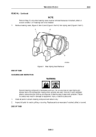
Connect hook tester scale (Figure 6, Item 3) in bolt hole (Figure 6, Item 2).
2.
Tighten adjusting nut (Figure 6, Item 4) and pull tester scale downward.
NOTE
Bearings are correctly adjusted when pull on scale required to rotate seat is 25 to 33 lb
(11
to
15
kg). This is equal to 15 to 20 lb-ft (20 to 27 N·m) preload on bearings.
3.
Note pull required to rotate spring seat (Figure 6, Item 1) around cross tube (Figure 5, Item 1).
1
2
3
4
M9191DAA
Figure 6.
Rear Spring Seat Adjustment.
4.
Install key washer (Figure 5, Item 12) and locking nut (Figure 5, Item 11). Repeat Steps (2) and (3) to ensure
bearing adjustment does not change. Tighten locking nut 150 to 160 lb-ft (203 to 217 N·m).
5.
Install gasket (Figure 5, Item 10) and spring seat cap (Figure 5, Item 9) on spring seat (Figure 5, Item 15) with
six lockwashers (Figure 5, Item 7) and screws (Figure 5, Item 8). Tighten screw 16 to 20 lb-ft (22 to 27 N·m).
END OF TASK
TM 9-2320-272-23-3
0540
0540-8
Back to Top


