TM-9-2320-272-23-3 - Page 253 of 1469
INSTALLATION
1.
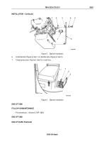
Install o-ring (Figure 2, Item 9) and modulator (Figure 2, Item 10) on transmission (Figure 2, Item 16) with
retaining bracket (Figure 2, Item 7) and screw (Figure 2, Item 8). Tighten screw 16 to 20 lb-ft (22 to 27 N·m).
NOTE
Clamp and shim must align on modulator cable.
2.
Install shim (Figure 2, Item 3) and modulator cable (Figure 2, Item 4) on bracket (Figure 2, Item 1) with clamp
(Figure 2, Item 5), two screws (Figure 2, Item 6), and locknuts (Figure 2, Item 2).
NOTE
Locate modulator cable away from sharp edges and avoid sharp bends.
3.
Install modulator cable (Figure 2, Item 4) on transmission bracket (Figure 2, Item 14) with modulator cable
clamp (Figure 2, Item 13), speedometer cable clamp (Figure 2, Item 11), screw (Figure 2, Item 12), and locknut
(Figure 2, Item 15).
TM 9-2320-272-23-3
0365
0365-4
Back to Top

