TM-9-2320-272-23-3 - Page 255 of 1469
ADJUSTMENT
NOTE
Assistant will help with Steps (1) through (4).
1.
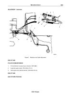
Move throttle lever (Figure 3, Item 4) on fuel pump (Figure 3, Item 14) to FULLY OPEN position and hold.
2.
Pull threaded end of modulator cable (Figure 3, Item 10) out to STOP position.
3.
Loosen jamnut (Figure 3, Item 6) and thread modulator link (Figure 3, Item 10) onto modulator cable
(Figure
3,
Item 8) until front of slot aligns with hole in throttle lever (Figure 3, Item 4). Continue to loosen
jamnut as needed to position modulator link.
4.
Back off modulator link (Figure 3, Item 10) two turns to provide free pin clearance and tighten jamnut
(Figure
3,
Item 6).
5.
Install modulator link (Figure 3, Item 10) on throttle lever (Figure 3, Item 4) with screw (Figure 3, Item 3) and
locknut (Figure 3, Item 5).
NOTE
•
Assistant will help with Steps (6) and (7).
•
Ensure throttle lever is still in FULLY OPEN position.
6.
Loosen throttle stopscrew (Figure 3, Item 11) and jamnut (Figure 3, Item 12) on cab floor (Figure 3, Item 1).
Loosen nut (Figure 3, Item 13) as needed.
7.
Adjust stopscrew (Figure 3, Item 11) to barely touch cab floor (Figure 3, Item 1) side of accelerator pedal
(Figure
3, Item 2). Tighten jamnut (Figure 3, Item 12) and nut (Figure 3, Item 13).
8.
Release throttle lever (Figure 3, Item 4) on fuel pump (Figure 3, Item 14).
9.
Install modulator return spring (Figure 3, Item 9) on modulator link (Figure 3, Item 10) and bracket
(Figure
3,
Item 7).
TM 9-2320-272-23-3
0365
0365-6
Back to Top


