TM-9-2320-272-23-3 - Page 263 of 1469
REMOVAL - Continued
NOTE
Tag all leads for installation.
12.
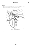
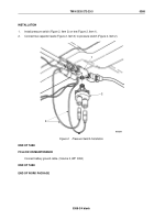
Disconnect capacitor leads (Figure 2, Items 8 and 9) from transmission 5th gear lock-up pressure switch
(Figure
2,
Item 7).
13.
Remove pressure switch (Figure 2, Item 7) from tee (Figure 2, Item 6).
14.
Disconnect capacitor leads (Figure 2, Items 2, 12, and 15) from leads (Figure 2, Items 1, 13, and 14).
15.
Remove screw (Figure 2, Item 10), lockwasher (Figure 2, Item 11), tee (Figure 2, Item 6), and capacitor
(Figure
2,
Item
5) from body (Figure 2, Item 3). Discard lockwasher.
16.
Remove clamp (Figure 2, Item 4) from capacitor (Figure 2, Item 5).
1
2
3
4
5
6
7
8
9
10
11
12
13
14
15
M8062DAA
Figure 2.
Capacitor Removal.
TM 9-2320-272-23-3
0367
0367-4
Back to Top


