TM-9-2320-272-23-3 - Page 301 of 1469
INSTALLATION
WARNING
•
Keep rear of transmission tilted slightly downward at all times to prevent converter from
sliding off. Failure to comply may result in damage to equipment, injury, or death to
personnel.
•
Torque converter must be installed with transmission as an assembly. Failure to comply
may result in damage to equipment, injury, or death to personnel.
1.
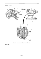
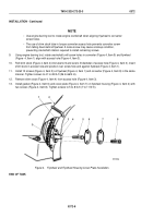
Install four guide screws (Figure 3, Item 14) at 9, 11, 1, and 3 o’clock positions on flywheel housing
(Figure
3,
Item 1).
2.
Place transmission (Figure 3, Item 3) on transmission jack (Figure 3, Item 7).
3.
Remove four nuts (Figure 3, Item 2), washers (Figure 3, Item 13), and screws (Figure 3, Item 9) from retaining
strap (Figure 3, Item 8) and transmission (Figure 3, Item 3).
4.
Remove two screws (Figure 3, Item 11) and retaining strap (Figure 3, Item 8) from converter
(Figure
3,
Item
10).
5.
Position gasket (Figure 3, Item 2) on guide screws (Figure 3, Item 14) and flywheel housing
(Figure
3,
Item
1).
CAUTION
Maintain transmission alignment to flywheel housing during installation to prevent damage
to
converter.
6.
Raise transmission (Figure 3, Item 3), align with guide screws (Figure 3, Item 14), and seat against flywheel
housing (Figure 3, Item 1).
7.
Install transmission (Figure 3, Item 3) on flywheel housing (Figure 3, Item 1) with clamp (Figure 3, Item 4),
eight lockwashers (Figure 3, Item 5), and screws (Figure 3, Item 6). Tighten screws to 36 to 40 lb-ft
(49 to 54 N·m).
8.
Remove four guide screws (Figure 3, Item 14) and install remaining four lockwashers (Figure 3, Item 5) and
screws (Figure 3, Item 6). Tighten screws to 36 to 40 lb-ft (49 to 54 N·m).
TM 9-2320-272-23-3
0372
0372-6
Back to Top

