TM-9-2320-272-23-3 - Page 363 of 1469
INSTALLATION
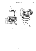
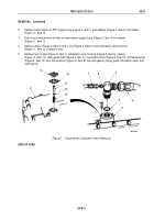
1.
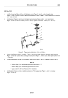
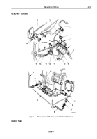
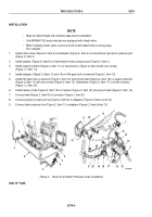
Install valve spring (Figure 3, Item 5), lubrication valve (Figure 3, Item 4), and valve guide tube
(Figure
3,
Item
3) in bore (Figure 3, Item 6) of transmission (Figure 3, Item 7). Ensure raised side of lubrication
valve faces outward.
2.
Install gasket (Figure 3, Item 2) and lubrication valve housing (Figure 3, Item 1) on transmission
(Figure
3,
Item
7) with two screws (Figure 4, Item 7). Tighten screws 9 to 11 lb-ft (12
to
15
N·m).
M7035DAA
7
1
2
3
4
5
6
Figure 3.
Transmission Lubrication Valve Installation.
3.
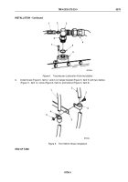
Place o-ring (Figure 4, Item 5) on elbow (Figure 4, Item 3) and install elbow on lubrication valve housing
(Figure
4,
Item
6). Tighten elbow until aligned and jamnut (Figure 4, Item 8) seats, then tighten jamnut until
o-ring seats.
4.
Connect transmission oil filter-to-transmission supply hose (Figure 4, Item 4) on elbow (Figure 4, Item 3).
NOTE
•
Perform Step (5) for vehicles equipped with transmission PTO.
•
Perform Step (6) for vehicles equipped with front winch.
•
Apply sealant to all male threads before installation.
5.
Install adapter (Figure 4, Item 2) and transmission-to-PTO supply hose (Figure 4, Item 1) on elbow
(Figure
4,
Item
3).
TM 9-2320-272-23-3
0378
0378-4
Back to Top

