TM-9-2320-272-23-3 - Page 437 of 1469
INSTALLATION
1.
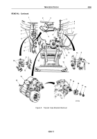
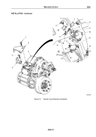
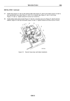
Install control valve bracket (Figure 10, Item 2) on transfer case (Figure 10, Item 3) with three screws
(Figure
10,
Item
1). Finger-tighten screws.
2.
Install interlock valve bracket (Figure 10, Item 4) on transfer case (Figure 10, Item 3) with two screws
(Figure
10,
Item
5). Tighten screws (Figure 10, Items 1 and 5) 30 to 40 lb-ft (41 to 54 N·m).
3.
Install interlock valve (Figure 10, Item 11) on interlock valve bracket (Figure 10, Item 4) with two screws
(Figure
10,
Item
15).
4.
Install elbow (Figure 10, Item 12) on air cylinder cover (Figure 10, Item 13).
5.
Install elbow (Figure 10, Item 9) on interlock air cylinder (Figure 10, Item 10).
6.
Install vent tees (Figure 10, Items 7 and 16) and fitting (Figure 10, Item 8) on inspection cover
(Figure
10,
Item
14).
7.
Install three elbows (Figure 10, Item 6) on vent tees (Figure 10, Items 7 and 16).
8.
Using lifting device, position transfer case (Figure 10, Item 3) on hydraulic jack.
TM 9-2320-272-23-3
0386
0386-14
Back to Top

