TM-9-2320-272-23-3 - Page 440 of 1469
INSTALLATION - Continued
11.
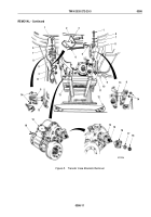
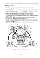
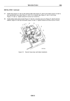
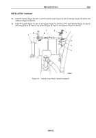
Position hydraulic jack (Figure 12, Item 12) and transfer case (Figure 12, Item 13) under vehicle.
12.
Raise transfer case (Figure 12, Item 13) in position high enough to allow for installation of mounting brackets
(Figure 12, Item 8).
13.
Install two mounting brackets (Figure 12, Item 8) on transfer case (Figure 12, Item 13) with seven locknuts
(Figure
12, Item 14). Tighten locknuts 125 to 135 lb-ft (170 to 183 N·m).
14.
Install right frame bracket (Figure 12, Item 3) on frame (Figure 12, Item 4) with three screws
(Figure
12,
Item
5) and locknuts (Figure 12, Item 2). Tighten locknuts 120 lb-ft (163
N·m).
15.
Place three insulators (Figure 12, Item 9) between mounting brackets (Figure 12, Item 8) and frame brackets
(Figure 12, Item 10).
16.
Slowly lower transfer case (Figure 12, Item 13) and align holes in mounting brackets (Figure 12, Item 8),
insulators (Figure 12, Item 9), and frame brackets (Figure 12, Item 10).
17.
Install three insulators (Figure 12, Item 7), washers (Figure 12, Item 6), screws (Figure 12, Item 1), and locknuts
(Figure 12, Item 11) on mounting brackets (Figure 12, Item 8) and frame brackets (Figure 12, Item 10). Tighten
locknuts 50 to 60 lb-ft (68 to 81 N·m).
18.
Remove hydraulic jack (Figure 12, Item 12) from transfer case (Figure 12, Item 13) and vehicle.
M7074DAA
1
6
7
8
9
4
11
14
8
13
13
2
3
4
5
1
6
7
8
9
10
8
14
12
11
13
10
Figure 12.
Transfer Case Lines and Cables Installation.
TM 9-2320-272-23-3
0386
0386-17
Back to Top

