TM-9-2320-272-23-3 - Page 446 of 1469
INSTALLATION - Continued
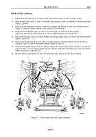
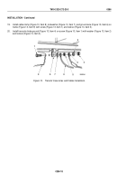
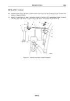
35.
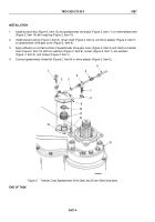
Install PTO cable (Figure 18, Item 1) on PTO selector lever (Figure 18, Item 7) with pin (Figure 18, Item 8) and
cotter pin (Figure 18, Item 9).
36.
Install PTO cable (Figure 18, Item 1) and spacer (Figure 18, Item 4) on PTO cable bracket (Figure 18, Item 5)
with clamp (Figure 18, Item 2), two screws (Figure 18, Item 3), and locknuts (Figure 18, Item 6).
M9898DAA
7
8
9
1
2
3
5
6
4
Figure 18.
Transfer Case Power Takeoff Installation.
TM 9-2320-272-23-3
0386
0386-23
Back to Top

