TM-9-2320-272-23-3 - Page 507 of 1469
REMOVAL
1.
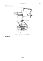
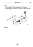
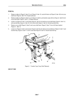
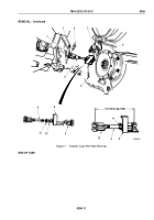
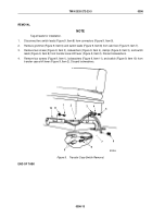
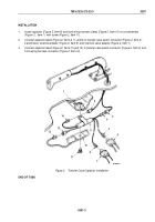
Remove cotter pin (Figure 7, Item 5), pin (Figure 7, Item 4), and transfer case shift rod (Figure 7, Item 6) from
shift shaft (Figure 7, Item 3). Discard cotter pin.
2.
Remove cotter pin (Figure 7, Item 7), pin (Figure 7, Item 2), and transfer case shift rod (Figure 7, Item 6) from
cross shaft lever (Figure 7, Item 1). Discard cotter pin.
WARNING
Solvent cleaning compound is flammable and toxic. Do not use near an open flame and
always have a fire extinguisher nearby when solvents are used. Use only in well-ventilated
places, wear protective clothing, and dispose of cleaning rags in approved container. Failure
to comply may result in damage to equipment, injury, or death to personnel.
3.
Clean transfer case shift rod (Figure 7, Item 6) with cleaning compound solvent.
4.
Inspect transfer case shift rod (Figure 7, Item 6) for cracks and breaks. Replace shift rod if cracked or broken.
5.
Inspect valve cam (Figure 7, Item 8) for cracks, breaks, and bends. Replace valve cam if cracked, broken, or
bent.
NOTE
Perform Steps (6) through (9) if valve cam requires replacement.
6.
Place transfer case shift rod (Figure 7, Item 6) in vise.
7.
Remove clevis (Figure 7, Item 9), valve cam (Figure 7, Item 8), washer (Figure 7, Item 10), and jamnut
(Figure
7,
Item
11) from shift rod (Figure 7, Item 6).
8.
Install jamnut (Figure 7, Item 11), washer (Figure 7, Item 10), valve cam (Figure 7, Item 8), and clevis
(Figure
7,
Item
9) on shift rod (Figure 7, Item 6). Do not tighten jamnut.
9.
Remove transfer case shift rod (Figure 7, Item 6) from vise.
10.
Loosen jamnut (Figure 7, Item 11) if necessary.
11.
Adjust clevis (Figure 7, Item 12) until distance between centers of holes is 9-17/32 in. (24.2 cm).
12.
Tighten jamnut (Figure 7, Item 11).
TM 9-2320-272-23-3
0396
0396-10
Back to Top


