TM-9-2320-272-23-3 - Page 511 of 1469
INSTALLATION
1.
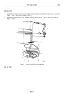
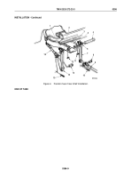
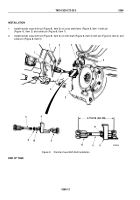
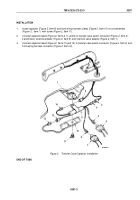
Install switch (Figure 10, Item 10) on transfer case shift lever (Figure 10, Item 2) with four lockwashers
(Figure
10,
Item
11) and screws (Figure 10, Item 1).
2.
Install two switch leads (Figure 10, Item 8) on transfer case shift lever (Figure 10, Item 2) with two clamps
(Figure 10, Item 3), lockwashers (Figure 10, Item 4), and screws (Figure 10, Item 5).
3.
Insert two switch leads (Figure 10, Item 8) through cab floor (Figure 10, Item 7) and connect to connectors
(Figure 10, Item 9).
4.
Install grommet (Figure 10, Item 6) around switch leads (Figure 10, Item 8) and install on cab floor
(Figure
10,
Item
7).
1
2
3
4
5
6
7
8
9
11
10
M7056DAA
Figure 10.
Transfer Case Switch Installation.
END OF TASK
FOLLOW-ON MAINTENANCE
Check transfer case shift lever for proper operation. Road test vehicle. (TM 9-2320-272-10)
END OF TASK
END OF WORK PACKAGE
TM 9-2320-272-23-3
0396
0396-14
Back to Top

