TM-9-2320-272-23-3 - Page 742 of 1469
INSTALLATION
1.
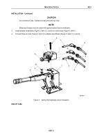
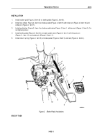
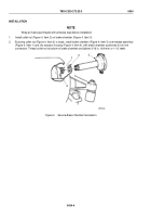
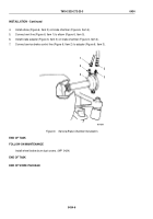
Install rubber pad (Figure 2, Item 8) on brake pedal (Figure 2, Item 9).
2.
Install two rollers (Figure 2, Item 6) on brake pedal (Figure 2, Item 9) with roller pin (Figure 2, Item 10) and
cotter pin (Figure 2, Item 7).
3.
Install pedal stop (Figure 2, Item 4) on brake pedal valve (Figure 2, Item 1) with jamnut (Figure 2, Item 3). Do
not tighten jamnut.
4.
Install brake pedal (Figure 2, Item 9) on brake pedal valve (Figure 2, Item 1) with fulcrum pin
(Figure
2,
Item
12) and cotter pin (Figure 2, Item 11).
5.
Install return spring (Figure 2, Item 5) on brake pedal (Figure 2, Item 9) and cab (Figure 2, Item 2).
M9533DAA
1
2
3
4
5
6
7
8
9
10
12
11
6
Figure 2.
Brake Pedal Installation.
END OF TASK
TM 9-2320-272-23-3
0433
0433-3
Back to Top

