TM-9-2320-272-23-4 - Page 136 of 1393
INSTALLATION
1.
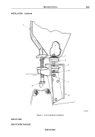
Position two insulators (Figure 2, Item 5) between cab (Figure 2, Item 1) and frame (Figure 2, Item 8).
2.
Install two washers (Figure 2, Item 3), springs (Figure 2, Item 2), and screws (Figure 2, Item 4) through
insulators (Figure 2, Item 5).
3.
Lower cab (Figure 2, Item 1) to frame (Figure 2, Item 7) and remove lifting device.
4.
Install two washers (Figure 2, Item 6) and locknuts (Figure 2, Item 7) on screws (Figure 2, Item 4) and tighten
until washers (Figure 2, Item 3) are even with cab (Figure 2, Item 1) floor.
M5199DAA
8
1
3
2
4
5
6
7
Figure 2.
Rear Cab Mount Installation.
END OF TASK
TM 9-2320-272-23-4
0569
0569-3
Back to Top


