TM-9-2320-272-23-4 - Page 483 of 1393
REMOVAL
NOTE
Tag wires for installation.
1.
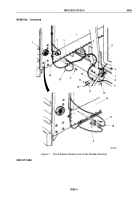
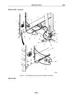
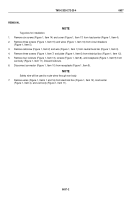
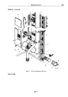
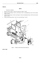
Remove six screws (Figure 1, Item 14) and cover (Figure 1, Item 17) from load center (Figure 1, Item 4).
2.
Remove three screws (Figure 1, Item 15) and wires (Figure 1, Item 16) from circuit breakers
(Figure 1, Item 5).
3.
Remove setscrew (Figure 1, Item 2) and wire (Figure 1, Item 1) from neutral buss bar (Figure 1, Item 3).
4.
Remove three screws (Figure 1, Item 7) and plate (Figure 1, Item 6) from electrical box (Figure 1, Item 12).
5.
Remove four locknuts (Figure 1, Item 13), screws (Figure 1, Item 8), and receptacle (Figure 1, Item 9) from
van body (Figure 1, Item 11). Discard locknuts.
6.
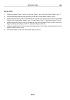
Disconnect connector (Figure 1, Item 10) from receptacle (Figure 1, Item 9).
NOTE
Safety wire will be used to route wires through van body.
7.
Remove wires (Figure 1, Items 1 and 16) from electrical box (Figure 1, Item 12), load center
(Figure 1, Item 4), and van body (Figure 1, Item 11).
TM 9-2320-272-23-4
0637
0637-2
Back to Top

