TM-9-2320-272-23-4 - Page 473 of 1393
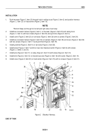
INSTALLATION
1.
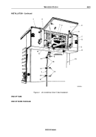
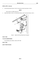
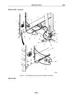
Push harness (Figure 2, Item 23) through hole in ceiling truss (Figure 2, Item 2) and position harness
(Figure
2,
Item
23) on load center (Figure 2, Item 15).
NOTE
Perform Steps (2) through (5) for left and right side of van body.
2.
Install two connector halves (Figure 2, Item 1) on harness (Figure 2, Item 23) and ceiling truss
(Figure
2,
Item
2) with two screws (Figure 2, Item 25) and grommet (Figure 2, Item 3).
3.
Install cover (Figure 2, Item 22) on van body (Figure 2, Item 26) with six screws (Figure 2, Item 24).
4.
Install two connector halves (Figure 2, Item 18) on harness (Figure 2, Item 23) and cover (Figure 2, Item 22)
with two screws (Figure 2, Item 17) and grommet (Figure 2, Item 19).
5.
Install grommet (Figure 2, Item 4) on van body (Figure 2, Item 26).
6.
Install wires (Figure 2, Item 7 and 8) on rear door blackout switch (Figure 2, Item 6) with screws
(Figure
2,
Items
5
and
9).
7.
Install wire (Figure 2, Item 11) on relay (Figure 2, Item 12) with screw (Figure 2, Item 10).
8.
Install wire (Figure 2, Item 13) on neutral buss bar (Figure 2, Item 16) with screw (Figure 2, Item 14).
9.
Install cover (Figure 2, Item 20) on load center (Figure 2, Item 15) with six screws (Figure 2, Item 21).
3
4
5
M3052DAA
1
2
26
6
7
8
9
10
11
12
13
14
15
16
17
18
19
20
21
22
23
24
25
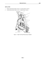
Figure 2.
Blackout Harness.
END OF TASK
TM 9-2320-272-23-4
0635
0635-4
Back to Top

