TM-9-2320-272-23-4 - Page 653 of 1393
INSTALLATION - Continued
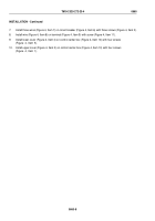
7.
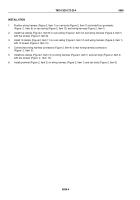
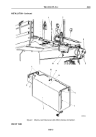
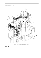
Install three wires (Figure 4, Item 7) on circuit breaker (Figure 4, Item 6) with three screws (Figure 4, Item 3).
8.
Install wire (Figure 4, Item 8) on terminal (Figure 4, Item 9) with screw (Figure 4, Item 11).
9.
Install lower cover (Figure 4, Item 4) on control center box (Figure 4, Item 10) with four screws
(Figure
4,
Item
5).
10.
Install upper cover (Figure 4, Item 2) on control center box (Figure 4, Item 10) with four screws
(Figure
4,
Item
1).
TM 9-2320-272-23-4
0660
0660-8
Back to Top

