TM-9-2320-272-23-4 - Page 660 of 1393
INSTALLATION - Continued
2.
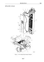
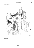
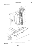
Install two wires (Figure 4, Item 4) on terminal (Figure 4, Item 5) with two screws (Figure 4, Item 3).
3.
Install upper cover (Figure 4, Item 2) on control center box (Figure 4, Item 6) with four screws
(Figure
4,
Item
1).
M10225DAA
3
2
1
4
5
6
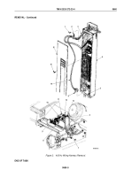
Figure 4.
Branched 400 Hz Receptacle Wiring Harness Installation.
END OF TASK
FOLLOW-ON MAINTENANCE
1.
Install ceiling filler and side panels.
2.
Connect battery ground cables. (Volume 2, WP
0350)
END OF TASK
END OF WORK PACKAGE
TM 9-2320-272-23-4
0661
0661-5/6 blank
Back to Top

