TM-9-2320-272-23-4 - Page 761 of 1393
ASSEMBLY - Continued
8.
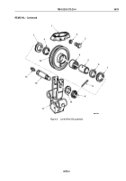
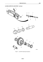
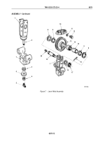
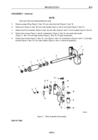
Using arbor press, install swivel (Figure 7, Item 1) with extension (Figure 7, Item 2) in frame
(Figure
7,
Item
7).
9.
With swivel (Figure 7, Item 1) and extension (Figure 7, Item 2) seated in frame (Figure 7, Item 7), install felt
washer (Figure 7, Item 3), washer (Figure 7, Item 6), and locknut (Figure 7, Item 4) on end of extension.
10.
Install grease fitting (Figure 7, Item 5) on end of extension (Figure 7, Item 2).
11.
Install bearing (Figure 7, Item 14), sleeve (Figure 7, Item 15), and two felt washers (Figure 7, Item 9) in sheave
(Figure 7, Item 13).
12.
Coat one side of each of two thrust washers (Figure 7, Item 8) with grease and install on sheave
(Figure
7,
Item
13) with grease side next to bearing (Figure 7, Item 14).
13.
Carefully place sheave (Figure 7, Item 13) and thrust washers (Figure 7, Item 8) in swivel (Figure 7, Item 1)
and install with screw (Figure 7, Item 19), washer (Figure 7, Item 18), and slotted nut (Figure 7, Item 17). Ensure
that slots in nut align with hole in screw.
14.
Install cotter pin (Figure 7, Item 16) in slots of nut (Figure 7, Item 17) and hole in screw (Figure 7, Item 19).
15.
Install grease fitting (Figure 7, Item 20) in head end of screw (Figure 7, Item 19).
16.
Position sheave guard (Figure 7, Item 10) over sheave (Figure 7, Item 13) and install on swivel
(Figure
7,
Item
1) with four lockwashers (Figure 7, Item 11) and screws (Figure 7, Item 12).
TM 9-2320-272-23-4
0678
0678-12
Back to Top

