TM-9-2320-272-23-4 - Page 763 of 1393
ASSEMBLY - Continued
NOTE
•
Both sets of trolley wheels are installed the same.
•
An arbor press may be required to perform Step (17).
17.
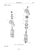
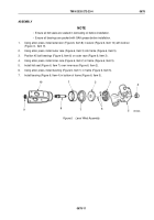
Install axle (Figure 8, Item 9) in frame (Figure 8, Item 10).
18.
Install thrust washer (Figure 8, Item 8) on axle (Figure 8, Item 9).
19.
Install bearing (Figure 8, Item 7) in wheel (Figure 8, Item 6).
20.
Install two washers (Figure 8, Item 4), felt washer (Figure 8, Item 5), wheel (Figure 8, Item 6), felt washer
(Figure 8, Item 5), two washers (Figure 8, Item 4), lockwasher (Figure 8, Item 3), and screw (Figure 8, Item 2)
on axle (Figure 8, Item 9).
21.
Install grease fitting (Figure 8, Item 1) on screw (Figure 8, Item 2).
22.
Place spring (Figure 8, Item 18) over poppet (Figure 8, Item 14) and install with nut (Figure 8, Item 19).
23.
Install poppet (Figure 8, Item 14) and latch (Figure 8, Item 20) in track (Figure 8, Item 11) with two nuts
(Figure
8, Item 21).
24.
Place level wind assembly (Figure 8, Item 10) on track (Figure 8, Item 11) and install with four lockwashers
(Figure 8, Item 23) and screws (Figure 8, Item 22).
25.
Install two stopscrews (Figure 8, Item 12) on track (Figure 8, Item 11) with each screw positioned with two nuts
(Figure 8, Item 13). Level wind (Figure 8, Item 10) receives final adjustment when winch (Figure 8, Item 17) is
mounted on vehicle.
END OF TASK
INSTALLATION
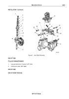
Install level wind assembly (Figure 8, Item 10) and track (Figure 8, Item 11) on winch (Figure 8, Item 17) with
four lockwashers (Figure 8, Item 16) and screws (Figure 8, Item 15).
TM 9-2320-272-23-4
0678
0678-14
Back to Top

