TM-9-2320-272-23-4 - Page 819 of 1393
INSTALLATION - Continued
5.
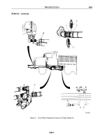
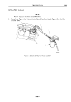
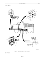
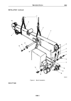
Using care not to bend tube (Figure 8, Item 3), connect hose (Figure 8, Item 4) to elbow (Figure 8, Item 5) and
tube (Figure 8, Item 2).
6.
Using care not to bend tube (Figure 8, Item 2), connect hose (Figure 8, Item 1) to tube and control valve elbow
(Figure 8, Item 15).
7.
Connect two hose ends (Figure 8, Item 16) as tagged to two control valve elbows (Figure 8, Item 14).
WARNING
Do not cross hoses during installation. Failure to comply may result in injury or death to
personnel.
8.
Connect two hose ends (Figure 8, Item 6) to two elbows (Figure 8, Item 7).
9.
Position two pairs of clamps (Figure 8, Item 9) on hoses (Figure 8, Item 12) and install clamps on two brackets
(Figure 8, Item 13) with two screws (Figure 8, Item 8) and locknuts (Figure
8,
Item
10).
10.
Install six tiedown straps (Figure 8, Item 11) as necessary over two hoses (Figure 8, Item 12).
TM 9-2320-272-23-4
0685
0685-12
Back to Top

