TM-9-2320-272-23-4 - Page 825 of 1393
INSTALLATION
WARNING
Before hoisting outer boom away from wrecker, ensure inner boom is properly secured to
outer boom as outlined in Step (2). Failure to comply may result in injury or death to personnel.
NOTE
If installing boom assembly, use hardware from old boom.
1.
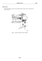
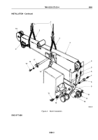
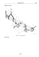
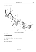
Install utility chain (Figure 2, Item 2) to secure inner boom (Figure 2, Item 18) to outer boom
(Figure
2,
Item
3).
2.
Attach two utility chains (Figure 2, Item 2) on outer boom (Figure 2, Item 3).
3.
Hoist outer boom (Figure 2, Item 3) over wrecker and position on turntable (Figure 2, Item 9).
4.
Assemble two sleeve bearings (Figure 2, Item 10) and sheave (Figure 2, Item 11), align sheave with holes in
turntable (Figure 2, Item 9) and outer boom (Figure 2, Item 3), and install boom on turntable with pivot pin
(Figure 2, Item 8) and locknut (Figure
2,
Item
12). Tighten locknut 800 to 1,000 lb-ft (1,185 to 1,356 N·m).
5.
Install grease fittings (Figure 2, Items 7 and 13) on pivot pin (Figure 2, Item 8).
6.
Connect two elevating cylinders (Figure 2, Item 14) to boom (Figure 2, Item 3) with two retaining pins
(Figure
2, Item 17), lockwashers (Figure 2, Item 16), and screws (Figure 2, Item 15). Tighten screws
44
to
61
lb-ft (60 to 83 N·m).
7.
Using lifting device and utility chains, lift outer boom (Figure 2, Item 3) and disconnect shipper braces from
boom.
8.
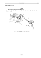
Connect cylinder extension hose (Figure 2, Item 6) and retracting hose (Figure 2, Item 5) to two boom adapter
elbows (Figure 2, Item 4).
9.
Remove utility chains from outer boom (Figure 2, Item 3).
TM 9-2320-272-23-4
0686
0686-4
Back to Top

