TM-9-2320-272-23-4 - Page 831 of 1393
INSTALLATION
1.
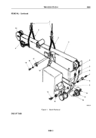
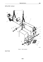
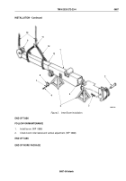
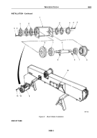
Attach utility chain (Figure 2, Item 12) to straddle balance point of inner boom (Figure 2, Item 13).
NOTE
•
Assistant will help with Steps (2) through (5).
•
Ensure pin hole in extension cylinder is parallel to top surface of inner boom.
2.
Attach lifting device (Figure 2, Item 10) to chain (Figure 2, Item 12), align inner boom (Figure 2, Item 13) with
outer boom (Figure 2, Item 1) and start inner boom into outer boom.
NOTE
If a second lifting device is not available, use sheave end of inner boom to permit transfer of
chain and lifting device.
3.
Remove chain (Figure 2, Item 12) from inner boom (Figure 2, Item 13).
4.
Attach utility chain (Figure 2, Item 12) and lifting device (Figure 2, Item 10) to sheave (Figure 2, Item 9) of inner
boom (Figure 2, Item 13).
5.
While adjusting position of sheave (Figure 2, Item 9) end of inner boom (Figure 2, Item 13), slide inner boom
into outer boom (Figure 2, Item 1) until holes in front of outer boom and extension cylinder (Figure 2, Item 4)
align.
6.
Install extension cylinder (Figure 2, Item 4) on outer boom (Figure 2, Item 1) with pin (Figure 2, Item 2) and
cotter pin (Figure 2, Item 3).
7.
Remove lifting device (Figure 2, Item 10) and chain (Figure 2, Item 12) from sheave (Figure 2, Item 9).
8.
Install two boom stops (Figure 2, Item 8) on outer boom (Figure 2, Item 1) with eight lockwashers
(Figure
2,
Item
7) and screws (Figure 2, Item 6).
TM 9-2320-272-23-4
0687
0687-4
Back to Top

