TM-9-2320-272-23-4 - Page 829 of 1393
REMOVAL
WARNING
•
Assistant must remain at crane controls until removal operation is completed. Injury to
personnel may result if boom control lever is accidentally engaged while work is being
done between raised boom and swivel base. Failure to comply may result in injury or
death to personnel.
•
All personnel must stand clear during hoisting operations. A snapped cable, or swinging
or shifting load, may occur. Failure to comply may result in injury or death to personnel.
NOTE
Extension cylinder will be removed and installed with the inner boom during this procedure.
1.
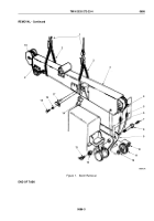
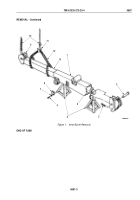
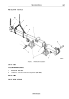
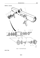
Remove cotter pin (Figure 1, Item 3) and pin (Figure 1, Item 2) from extension cylinder (Figure 1, Item 4) and
outer boom (Figure 1, Item 1). Discard cotter pin.
2.
Remove eight screws (Figure 1, Item 6), lockwashers (Figure 1, Item 7), and two boom stops
(Figure
1,
Item
8) from outer boom (Figure 1, Item 1). Discard lockwashers.
WARNING
Inner boom must be supported at sheave to prevent tilting until hoist chain can be properly
positioned around inner boom. Failure to comply may result in injury or death to personnel.
3.
Attach lifting device (Figure 1, Item 10) to sheave (Figure 1, Item 9) of inner boom (Figure 1, Item 13).
4.
While assistant monitors and adjusts lifting device (Figure 1, Item 10), slowly pull inner boom
(Figure
1,
Item
13) out of outer boom (Figure 1, Item 1) until utility chain (Figure 1, Item 12) can be positioned
around inner boom.
NOTE
If only one lifting device is available, support must be provided under sheave end of inner
boom while transferring lifting hook to utility chain on inner boom.
5.
Attach lifting device (Figure 1, Item 10) to utility chain (Figure 1, Item 12) on inner boom (Figure 1, Item 13)
and remove inner boom from outerboom (Figure 1, Item 1).
6.
Place inner boom (Figure 1, Item 13) on jack stands (Figure 1, Item 5) and remove lifting device
(Figure
1,
Item
10) and utility chain (Figure 1, Item 12) from inner boom.
TM 9-2320-272-23-4
0687
0687-2
Back to Top

