TM-9-2320-272-23-4 - Page 955 of 1393
REMOVAL - Continued
2.
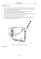
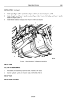
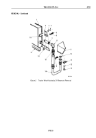
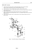
While holding nut (Figure 2, Item 15), disconnect oil supply line (Figure 2, Item 14) from elbow
(Figure
2,
Item
8).
3.
Remove four screws (Figure 2, Item 13), lockwashers (Figure 2, Item 12), two split flanges (Figure 2, Item 11),
oil supply hose (Figure 2, Item 14), and o-ring (Figure 2, Item 10) from hydraulic oil pump (Figure 2, Item 9).
Discard lockwashers and o-ring.
4.
Remove two locknuts (Figure 2, Item 4), washers (Figure 2, Item 3), and U-bolt (Figure 2, Item 18) from nipple
support (Figure 2, Item 2). Discard locknuts.
5.
Remove elbow (Figure 2, Item 8) and nipple (Figure 2, Item 7) from reservoir (Figure 2, Item 1).
6.
Remove two locknuts (Figure 2, Item 16), screws (Figure 2, Item 5), washers (Figure 2, Item 6), and nipple
support (Figure 2, Item 2) from reservoir base (Figure 2, Item 17). Discard locknuts.
TM 9-2320-272-23-4
0702
0702-4
Back to Top


