TM-9-2320-272-23-4 - Page 961 of 1393
INSTALLATION - Continued
8.
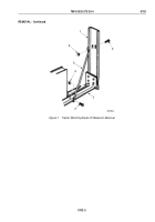
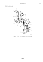
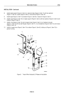
Install nipple support (Figure 5, Item 2) on reservoir base (Figure 5, Item 17) with two washers
(Figure
5,
Item
6), screws (Figure 5, Item 5), and locknuts (Figure 5, Item 16).
9.
Install nipple (Figure 5, Item 7) and elbow (Figure 5, Item 8) on reservoir (Figure 5, Item 1).
10.
Install U-bolt (Figure 5, Item 18) on nipple support (Figure 5, Item 2) with two washers (Figure 5, Item 3) and
locknuts (Figure 5, Item 4).
11.
Install o-ring (Figure 5, Item 10) and oil supply hose (Figure 5, Item 14) on hydraulic oil pump
(Figure
5,
Item
9) with two split flanges (Figure 5, Item 11), four lockwashers (Figure 5, Item 12), and screws
(Figure 5, Item 13).
12.
Install oil supply hose (Figure 5, Item 14) on elbow (Figure 5, Item 8), holding nut (Figure 5, Item 15) to
prevent
turning.
1
2
3 4
5
6
7
8
15
16
17
18
9
11
10
12
13
11
14
M5280DAA
Figure 5.
Tractor Winch Hydraulic Oil Reservoir Installation.
TM 9-2320-272-23-4
0702
0702-10
Back to Top

