TM-9-2320-272-23-5 - Page 343 of 623
INSTALLATION - Continued
NOTE
•
Wrap all male pipe threads with antiseize tape before installation
•
Preform Steps (11) through (13) for rear-rear axle exhaust valve.
11.
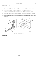
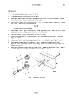
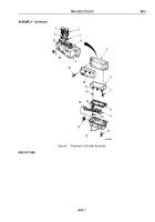
Install reducers (Figure 4, Items 24 and 28) and elbows (Figure 4, Items 23, 25, and 29) on relief safety valve
(Figure 4, Item 9).
12.
Connect air lines (Figure 4, Items 22 and 30) to elbow (Figure 4, Items 23 and 29).
13.
Insert sleeve (Figure 4, Item 26) on air line (Figure 4, Item 27), and connect air line to elbow
(Figure
4,
Item
25).
NOTE
Perform Steps (6) through (8) for forward-rear axle relief safety valve.
14.
Install reducers (Figure 4, Items 6 and 10), elbows (Figure 4, Items 7 and 12) and tee (Figure 4, Item 3) on
relief safety valve (Figure 4, Item 9).
15.
Connect air lines (Figure 4, Items 8 and 11) on elbows (Figure 4, Items 7 and 12).
16.
Insert sleeves (Figure 4, Items 2 and 4) on air lines (Figure 4, Items 1 and 5), and connect air lines to tee
(Figure 4, Item 3).
NOTE
Perform Steps (17) through (19) for front axle relief safety valve.
17.
Install reducers (Figure 4, Items 13 and 18), connectors (Figure 4, Items 14 and 16), and elbow
(Figure
4,
Item
21) on relief safety valve (Figure 4, Item 9).
18.
Connect air lines (Figure 4, Items 15 and 17) to connectors (Figure 4, Items 14 and 16).
19.
Insert sleeve (Figure 4, Item 20) on air line (Figure 4, Item 19), and connect air line to elbow
(Figure
4,
Item
21).
TM 9-2320-272-23-5
0809
0809-6
Back to Top


