TM-9-2320-272-23-5 - Page 348 of 623
DISASSEMBLY
1.
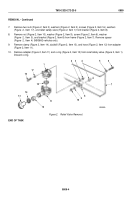
Remove nut (Figure 2, Item 8) from solenoid receptacle (Figure 2, Item 9), and remove six screws
(Figure
2,
Item
7), solenoid protector (Figure 2, Item 6), and gasket (Figure 2, Item 4) from cover plate
(Figure
2,
Item
2). Discard solenoid protector and gasket.
NOTE
Mark wiring harnesses to correspond to C, D, and S marks on base plate.
2.
Remove three nuts (Figure 2, Item 5), wiring harness (Figure 2, Item 10), three gaskets (Figure 2, Item 11),
and seats (Figure 2, Item 12) from studs (Figure 2, Item 13) on cover plate (Figure 2, Item 2).
3.
Remove six screws (Figure 2, Item 15) and base plate (Figure 2, Item 14) from valve body (Figure 2, Item 1).
4.
Remove four screws (Figure 2, Item 3) and cover plate (Figure 2, Item 2) from valve body (Figure
2,
Item
1).
NOTE
Mark location and position of valve cartridges for installation.
5.
Using access through orifice passages (Figure 2, Item 19), carefully pry out valve cartridge (Figure 2, Item 21)
and two valve cartridges (Figure 2, Item 16) from valve body ports (Figure 2, Item 18). Discard cartridges.
6.
Remove three o-rings (Figure 2, Item 17) and five o-rings (Figure 2, Item 20) from valve body
(Figure
2,
Item
1). Discard o-rings.
M6334DAA
17
20
18
21
16
17
19
1
9
10 11
12
13
8
7
6
5
4
3
2
1
14
15
Figure 2.
Pneumatic Controller Disassembly.
END OF TASK
TM 9-2320-272-23-5
0810
0810-3
Back to Top

