TM-9-2320-272-23-5 - Page 357 of 623
REMOVAL
1.
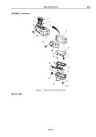
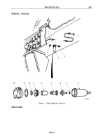
Disconnect two air lines (Figure 1, Item 1) from adapters (Figure 1, Item 2) on water separator
(Figure
1,
Item
3).
2.
Remove two adapters (Figure 1, Item 2) from water separator (Figure 1, Item 3).
3.
Remove body (Figure 1, Item 12) from bowl (Figure 1, Item 4).
4.
Remove stud (Figure 1, Item 7), filter (Figure 1, Item 8), louver (Figure 1, Item 9), gasket (Figure 1, Item 10),
and o-ring (Figure 1, Item 11) from body (Figure 1, Item 12). Discard filter, gasket, and o-ring.
5.
Remove automatic drain valve (Figure 1, Item 6) and o-ring (Figure 1, Item 5) from bowl (Figure 1, Item 4).
Discard o-ring.
6.
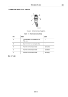
For General Inspection Instructions, refer to (WP
0819).
7.
Clean bowl (Figure 1, Item 4) with warm water and all other parts with soap and warm water.
WARNING
Eyeshields must be worn when cleaning with compressed air. Compressed air source will
not exceed 30 psi (207 kPa). Failure to comply may result in injury or death to personnel.
8.
From inside body (Figure 1, Item 12) blow out internal passages with compressed air.
TM 9-2320-272-23-5
0811
0811-2
Back to Top


