TM-9-2320-272-23-5 - Page 359 of 623
INSTALLATION
1.
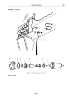
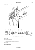
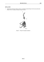
Coat lip of automatic drain valve (Figure 2, Item 6) with grease and install o-ring (Figure 2, Item 5) and automatic
drain valve (Figure 2, Item 6) in bowl (Figure 2, Item 4).
2.
Install o-ring (Figure 2, Item 11), gasket (Figure 2, Item 10), louver (Figure 2, Item 9), and filter
(Figure
2,
Item
8) on body (Figure 2, Item 12) with stud (Figure 2, Item 7).
3.
Install body (Figure 2, Item 12) on bowl (Figure 2, Item 4).
4.
Install two adapters (Figure 2, Item 2) on water separator (Figure 2, Item 3).
5.
Connect two air lines (Figure 2, Item 1) to adapters (Figure 2, Item 2).
TM 9-2320-272-23-5
0811
0811-4
Back to Top


