TM-9-2320-272-23-5 - Page 351 of 623
ASSEMBLY
1.
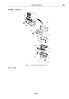
Install three o-rings (Figure 4, Item 3) on valve body ports (Figure 4, Item 4) and five o-rings
(Figure
4,
Item
20) on valve body ports (Figure 4, Item 21).
2.
Apply a thin coat of petrolatum to two valve cartridges (Figure 4, Item 2) and valve cartridge
(Figure
4,
Item
1), and install valve cartridges on valve body (Figure 4, Item 5).
3.
Install cover plate (Figure 4, Item 6) on valve body (Figure 4, Item 5) with four screws (Figure 4, Item 7).
4.
Install base plate (Figure 4, Item 18) on valve body (Figure 4, Item 5) with six screws (Figure 4, Item 19).
NOTE
Ensure marked wiring harness ends correspond to C, D, and S marks on base plate.
5.
Install three seats (Figure 4, Item 16), gaskets (Figure 4, Item 15), and wiring harness (Figure 4, Item 9) on
cover plate studs (Figure 4, Item 17) with three nuts (Figure 4, Item 10).
6.
Install gasket (Figure 4, Item 8) on solenoid protector (Figure 4, Item 12).
7.
Route solenoid receptacle (Figure 4, Item 14) through hole in solenoid protector (Figure 4, Item 12), and install
solenoid receptacle on solenoid protector with nut (Figure 4, Item 13).
8.
Install solenoid protector (Figure 4, Item 12) on cover plate (Figure 4, Item 6) with six screws
(Figure
4,
Item
11).
TM 9-2320-272-23-5
0810
0810-6
Back to Top

