TM-9-2320-272-23-5 - Page 347 of 623
REMOVAL
1.
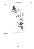
Disconnect connector (Figure 1, Item 9) from solenoid receptacle (Figure 1, Item 8).
2.
Disconnect air lines (Figure 1, Items 3 and 5) from elbows (Figure 1, Items 2 and 6).
3.
Remove relief valve (Figure 1, Item 4) and elbows (Figure 1, Items 2 and 6) from pneumatic controller
(Figure
1, Item 7).
4.
Remove four screws (Figure 1, Item 1), pneumatic controller (Figure 1, Item 7), and two spacers
(Figure
1,
Item
13) from mounting plate (Figure 1, Item 11).
5.
Remove three screws (Figure 1, Item 12) and mounting plate (Figure 1, Item 11) from cab floor
(Figure
1,
Item
10).
M6332DAA
1
5
3
2
4
6
7
13
8
9
10
11
12
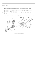
Figure 1.
Pneumatic Controller Removal.
END OF TASK
TM 9-2320-272-23-5
0810
0810-2
Back to Top


