TM-9-2320-272-23-5 - Page 68 of 623
REMOVAL - Continued
NOTE
Left and right rear post assemblies are removed the same way. This procedure is for the right
rear post assembly.
9.
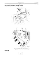
Remove two locknuts (Figure 4, Item 3) and U-bolt (Figure 4, Item 7) from right rear cab support
(Figure
4,
Item
4). Discard locknuts.
10.
Remove right rear post assembly (Figure 4, Item 2) from U-bolts (Figure 4, Item 7) and (Figure 4, Item 5) on
right rear cab support (Figure 4, Item 4).
11.
Remove two cotter pins (Figure 4, Item 1) and pin (Figure 4, Item 8) from bottom hole in right rear post assembly
(Figure 4, Item 2). Discard cotter pins.
12.
Remove four locknuts (Figure 4, Item 3) and U-bolts (Figure 4, Item 6) and (Figure 4, Item 5) from right rear
cab support (Figure 4, Item 4). Discard locknuts.
M6299DAA
4
3
1
2
1
8
7
6
5
Figure 4.
Weapon Station Removal.
TM 9-2320-272-23-5
0775
0775-5
Back to Top


