TM-9-2320-272-24-2 - Page 396 of 991
TM 9-2320-272-24-2
3-407. SWINGFIRE HEATER ELECTRICAL COMPONENTS REPLACEMENT
THIS TASK COVERS:
a. Electrical Connector Removal
b. Relay Removal
c. Circuit Breaker Removal
d. Thermal Switch Removal
e. Thermal Switch Installation
f. Circuit Breaker Installation
g. Relay Installation
h. Electrical Connector Installation
INITIAL SETUP:
APPLICABLE MODELS
All
REFERENCES (TM)
TM 9-2320-272-10
TM 9-2320-272-24P
TOOLS
General mechanic’s tool kit (Appendix E, Item 1)
EQUIPMEMT CONDITION
MATERIALS/PARTS
l
Parking brake set (TM 9-2320-272-10).
l
Battery ground cables disconnected (para. 3-126).
Lockwasher (Appendix D, Item 375)
Locknut (Appendix D, Item 291)
Three locknuts (Appendix D, Item 313)
Two locknuts (Appendix D, Item 276)
Antiseize compound (Appendix C, Item 62)
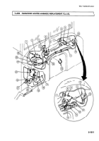
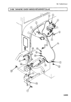
a. Electrical Connector Removal
1.
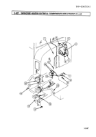
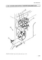
Loosen screw (10) and remove wire (9) from electrical connector (11).
2.
Remove nut (13), lockwasher (12), and electrical connector (11) from cab panel (14). Discard
lockwasher (12).
b. Relay Removal
NOTE
Tag all wires for installation.
1.
Remove four screws (8), clips (15), and wires (2) from relay (3) between dash panel (1) and
firewall (6).
2.
Remove two locknuts (4), screws (7), and relay (3) from bracket (5). Discard locknuts (4).
3-1004
Back to Top


