TM-9-2320-272-24-2 - Page 628 of 991
TM 9-2320-272-24-2
3-454. PNEUMATIC CONTROLLER AND RELIEF VALVE MAINTENANCE
THIS TASK COVERS:
a. Removal
b. Disassembly
c. Cleaning and Inspection
d. Assembly
e. Installation
INITIAL SETUP:
APPLICABLE MODELS
M939A2
TOOLS
General mechanic’s tool kit (Appendix E, Item 1)
Multimeter (Appendix E, Item 86)
MATERIALS/PARTS
Relief valve kit (Appendix D, Item 531)
Petrolatum (Appendix C, Item 53)
Antiseize tape (Appendix C, Item 72)
REFERENCES (TM)
TM 9-2320-272-10
TM 9-2320-272-24P
EQUIPMENT CONDITION
●
Air reservoirs drained ( TM 9-2320-272-10).
●
Pressure transducer removed (para. 3-453).
GENERAL SAFETY INSTRUCTIONS
When cleaning with compressed air, wear eyeshields
and ensure source pressure does not exceed 30 psi
(207 kPa).
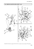
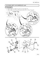
a. Removal
1.
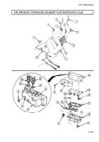
Disconnect connector (11) from solenoid receptacle (10).
2.
Disconnect air lines (5) and (7) from elbows (4) and (8).
3.
Remove relief valve (6) and elbows (4) and (8) from pneumatic controller (9).
4.
Remove four screws (3), pneumatic controller (9), and two spacers (2) from mounting plate (13).
5.
Remove three screws (1) and mounting plate (13) from cab floor (12).
b. Disassemble
1.
Remove nut (21) from solenoid receptacle (10), and remove six screws (20), solenoid protector (19),
and gasket (17) from cover plate (15). Discard solenoid protector (19) and gasket (17).
NOTE
Mark wiring harnesses to correspond to C, D, and S marks on
base plate.
2.
Remove three nuts (18), wiring harness (22), three gaskets (23), and seats (24) from studs (25) on
cover plate (15).
3.
Remove six screws (27) and base plate (26) from valve body (14).
4.
Remove four screws (16) and cover plate (15) from valve body (14).
NOTE
Mark location and position of valve cartridges for installation.
5.
Using access through orifice passages (32), carefully pry out valve cartridge (28) and two valve
cartridges (29) from valve body ports (31). Discard valve cartridges (28) and (29).
6.
Remove three O-rings (30) and five O-rings (33) from valve body (14). Discard O-rings (30) and (33).
3-1236
Back to Top


