TM-9-2320-272-24-3 - Page 310 of 799
TM 9-2320-272-24-3
4-102. FRONT DIFFERENTIAL 0IL SEAL REPLACEMENT
THIS TASK COVERS:
a. Removal
b. Installation
INITIAL SETUP:
APPLICABLE MODELS
All
TOOLS
General mechanic’s tool kit (Appendix E, Item 1)
Torque wrench (Appendix E, Item 145)
Mechanical puller (Appendix E, Item 102)
MATERIALS/PARTS
Gasket (Appendix D, Item 206)
Oil seal (Appendix D, Item 500)
Cotter pin (Appendix D, Item 61)
Gasket (Appendix D, Item 207)
GAA grease (Appendix C, Item 28)
Sealing compound (Appendix C, Item 30)
REFERENCES (TM)
TM 9-2320-272-10
TM 9-2320-272-24P
EQUIPMENT CONDITION
• Parking brake set (TM 9-2320-272-10).
• Rear wheels chocked (TM 9-2320-272-10).
• Propeller shaft removed (para. 3-149).
1.
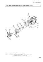
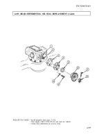
Remove cotter pin (1) and nut (11) from driveshaft (8). Discard cotter pin (1).
2.
Using mechanical puller, remove companion flange (2) from driveshaft (8).
CAUTION
Do not jam any tool between differential and pinion shaft retainer
when removing front bearing cover. Shims will be damaged.
3.
Remove eight screws (10), washers (9), front bearing cover (3), and gasket (6) from differential
carrier (7). Discard gasket (6).
4.
Remove oil seal (5) and gasket (4) from front bearing cover (3). Discard oil seal (5) and gasket (4).
b. Installation
1.
Position new gasket (4) in front bearing cover (3).
2.
Apply GAA grease to inside diameter of new oil seal (5). Apply sealing compound to outside
diameter of new oil seal (5).
3.
Install new oil seal (5) in front bearing cover (3).
4.
Apply sealing compound to mating surfaces of new gasket (6).
5.
Install new gasket (6) and front bearing cover (3) on differential carrier (7) with eight washers (9)
and screws (10). Tighten screws (10) 93-120 lb-ft (126-163 N•m).
6.
Install companion flange (2) on driveshaft (8) with nut (11). Tighten nut (11) 300-400 lb-ft
(407-542 N•m).
7.
Install new cotter pin (1) through nut (11) and driveshaft (8).
4-574
Back to Top

