TM-9-2320-272-24-3 - Page 584 of 799
4-176. FRONT
TM 9-2320-272-24-3
THIS TASK COVERS:
a. Removal
b. Installation
INITIAL SETUP:
APPLICABLE MODELS
M92/A1/A2, M928/Al/A2, M929/A1/A2,
M93/A1/A2, M932/A1/A2, M936/A1/A2
TOOLS
General mechanic’s tool kit (Appendix E, Item 1)
MATERIALS/PARTS
O-ring (Appendix D, Item 455)
Four lockwashers (Appendix D, Item 354)
Two locknuts (Appendix D, Item 294)
O-rings (Appendix D, Item 456)
Four lockwashers (Appendix D, Item 350)
REFERENCES (TM)
LO 9-2320-272-12
TM 9-2320-272-10
TM 9-2320-272-24P
EQUIPMENT CONDITION
Parking brake set (TM 9-2320-272-10).
Hydraulic oil reservoir drained (para. 4-188).
1.
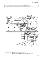
Remove setscrew (2) and driveshaft (1) from pump shaft (17).
2.
Remove four screws (8), lockwashers (9), two pipe flange swivels (6), tube (7), and O-ring (10) from
hydraulic pump (5). Discard O-ring (10) and lockwashers (9).
3.
Remove four screws (13), lockwashers (14), two pipe flange swivels (11), tube (12), and O-ring (15)
from hydraulic pump (5). Discard O-ring (15) and lockwashers (14).
4.
Remove two screws (3), locknuts (4), and hydraulic pump (5) from pump bracket (16). Discard
locknuts (4).
1.
Install pump (5) on bracket (16) with two screws (3) and new locknuts (4).
2.
Install new O-ring (10), two pipe flange swivels (6), and tube (7) on pump (5) with four new
lockwashers (9) and screws (8).
3.
Install new O-ring (15), two pipe flange swivels (11), and tube (12) on pump (5) with four new
lockwashers (14) and screws (13).
4.
Ensure key is in keyway and connect driveshaft (1) to pump shaft (17).
5.
Install setscrew (2) in driveshaft (1) and tighten.
4-848
Back to Top


