TM-9-2320-272-24-3 - Page 594 of 799
4-180. FRONT
TM 9-2320-272-24-3
THIS TASK COVERS:
a. Removal
b. Installation
INITIAL SETUP:
APPLICABLE MODELS
M925/A1/A2, M928/A1/A2, M929/A1/A2,
M930/A1/A2, M932/A1/A2, M936/A1/A2
TOOLS
General mechanic’s tool kit (Appendix E, Item 1)
MATERIALS/PARTS
Two locknuts (Appendix D, Item 306)
Six tiedown straps (Appendix D, Item 690)
Cap and plug set (Appendix C, Item 14)
REFERENCES (TM)
LO 9-2320-272-12
TM 9-232-272-10
TM 9-2320-272-24P
EQUIPMENT CONDITION
Parking brake set (TM 9-2320-272-10).
Hydraulic oil reservoir drained (para. 4-188).
GENERAL SAFETY INSTRUCTIONS
Do not cross hoses when installing.
Plug all openings to prevent dirt from entering and damaging
components.
NOTE
Remove and discard tiedown straps holding hoses to vehicle.
Have drainage container ready to catch oil.
Perform steps 1 through 4 for all vehicles except M936/A1/A2.
1.
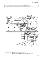
Holding filter adapter (10), loosen hose nut (9) and disconnect hose (7) from hydraulic oil reservoir (1).
2.
Remove nut (8), screw (4)`, and clamp (5) from mounting bracket (6).
3.
Loosen hose nut (3) and disconnect hose (7) from reservoir elbow (2).
4.
Remove hose (7) from reservoir (1).
NOTE
Clamp brackets remain attached to frame rail.
5.
Remove two locknuts (14), screws (12), and two pairs of hose clamps (13) from right frame rail (11)
and two hydraulic hoses (15). Discard locknuts (14).
4-858
Back to Top


